
Often, we, acousticians, are asked about the fundamentals of sound absorption.
We are also asked to explain sound absorption data received by suppliers & manufacturers of sound absorbing materials.
If you you need clarification on sound absorption, we wrote this article for you.
It explains
- what a sound absorber is
- how we rate the sound absorption capacity of materials.
- how we measure the sound absorption coefficient of materials.
Enjoy the read!
(See at the end the references used to confirm the concepts)

Do you want to be notified when new posts are published?
Why don’t you subscribe to Atelier Crescendo’s newsletter by clicking here?
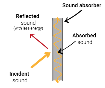
When sound strikes a material, some of its energy converts to heat, reducing the reflected sound energy.
The sound absorption of construction materials typically spans across narrow or wide frequency ranges, not single frequencies.
(if you need to understand what frequencies are read this article, and frequency bands read this article)
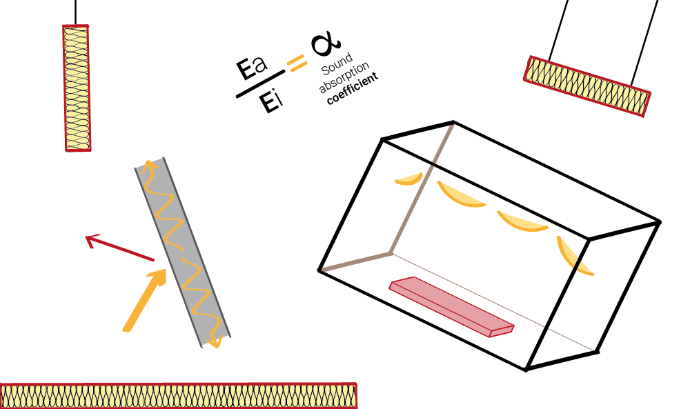
Various factors influence a material’s sound absorption in a space:
- the material type (hard, fibre-based, porous, etc)
- the thickness
- the finish (painted, cloth-covered, plastered, etc)
- the placement in the space
- the mounting method (on/off hard surface, free-hanging, etc)
Common sound absorptive solutions in construction use porous, fibrous, or cellular materials.
Other solutions utilize these materials with additional features like cavities, perforations or microperforations to enhance the sound absorption across specific frequency ranges.
Examples of materials will be presented in future posts.
This coefficient is the ratio of:
- the sound energy absorbed (Ea) by a material;
- divided by the sound energy incident (Ei) on the same material.
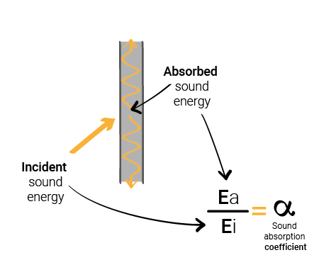
As the absorbed sound energy (Ea) increases, the sound absorption coefficient increases too.
Conversely, a decrease in absorbed sound energy results in a lower absorption coefficient.
Thus, better sound absorption yields a higher absorption coefficient, logically.
This method involves placing a sample of material at the end of a small tube.
Sound is emitted into the tube at different frequencies.
The sound absorption coefficient of the material is then derived by comparing the sound in the tube before and after it strikes the sample.
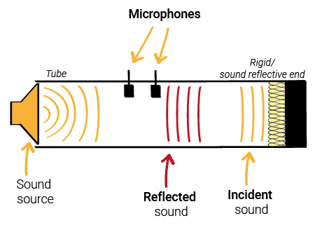
While more practical and time-efficient, this method is not preferred due to its restrictions on the type of material and mounting conditions.
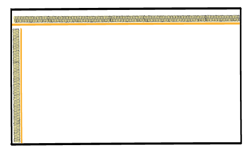
This method involves placing large samples or multiple samples of the material to be tested in a large & highly reverberant room.
The room typically comprises hard surfaces (walls, ceiling, and floor) that reflect sound, absorbing minimal to no sound, along with large sound reflective surfaces hung from the ceiling and sometimes positioned near the walls.
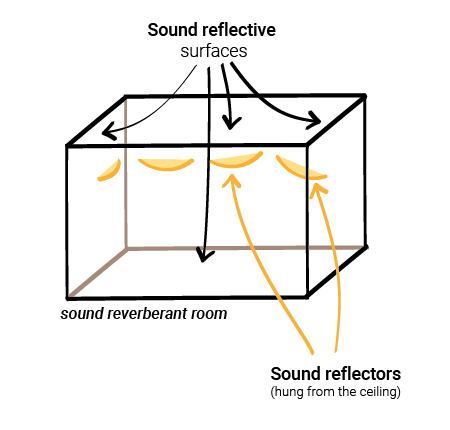
This setup aims to scatter sound extensively, creating a diffusive sound field within the room. This enables simulation of sound reaching the samples from all directions.
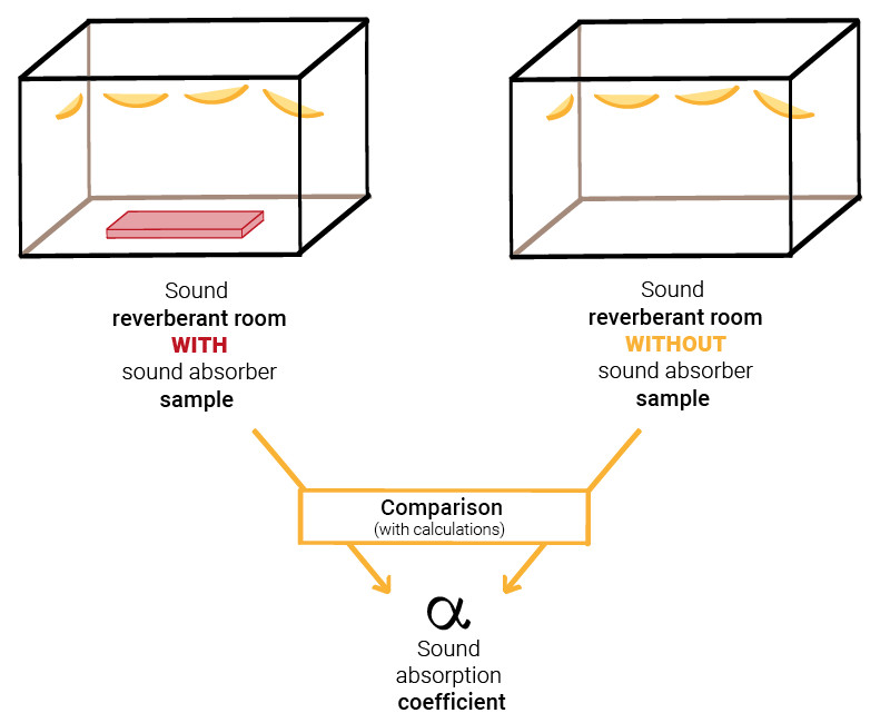
The sound absorption coefficient is calculated by comparing:
- Sound reverberation measurements without any materials.
- Sound reverberation measurements with the material under test.
While not as practical or time-effective as the impedance tube method, this approach offers the advantage of testing materials in more realistic mounting conditions. These include (but not only):
- Mounted directly against a hard surface.
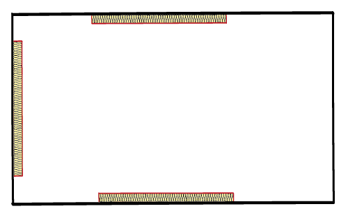
- Hung freely.
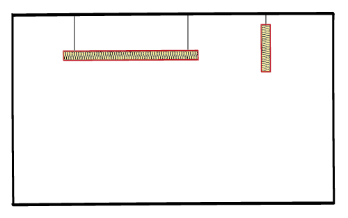
- Positioned within a cavity.
- Split into small samples.
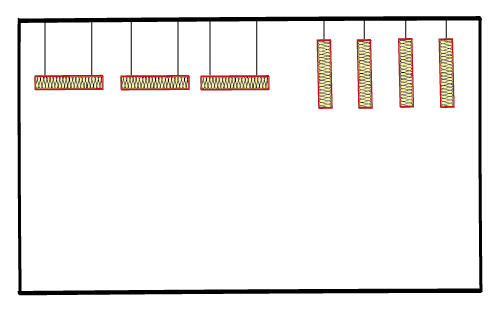
- And many others