
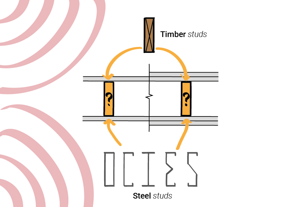
Wood vs metal studs: How wall stud materials impact the acoustic performance
When it comes to sound insulation in buildings, the material of the studs used in wall construction can make a significant […]
When it comes to sound insulation in buildings, the material of the studs used in wall construction can make a significant […]
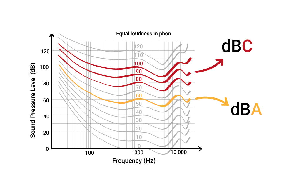
When measuring sound, it is not enough to simply capture the raw data — we need to understand how people
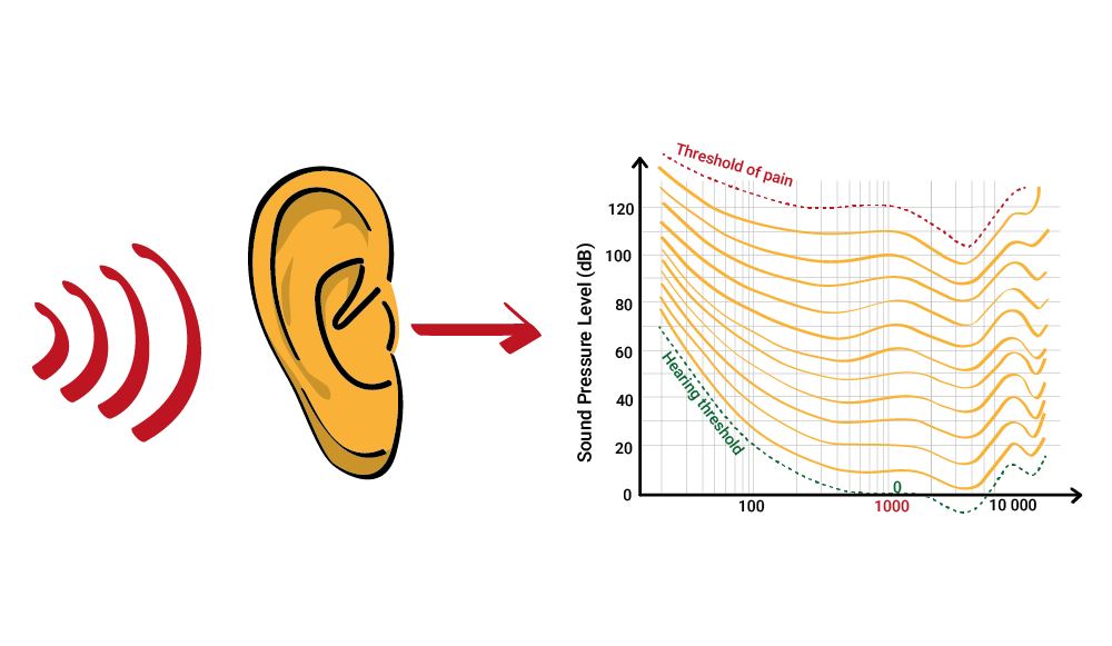
When designing spaces for music, speech, or everyday sound, it is important to understand how the human ear works. The
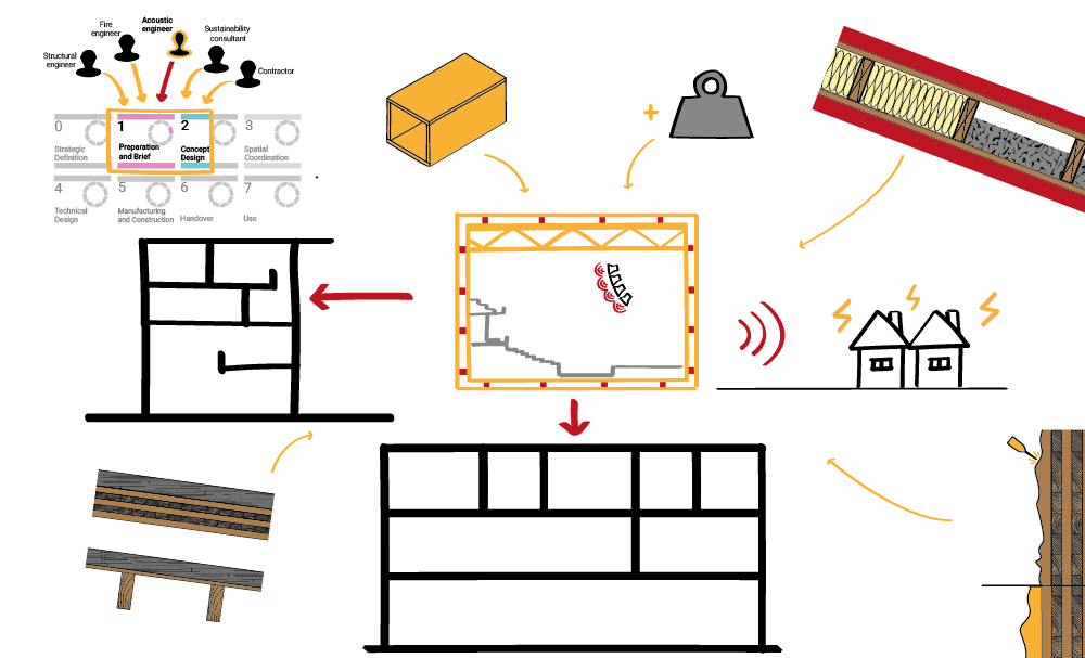
Designing entertainment venues—whether they are arenas, theatres, research halls or also concert halls—comes with unique acoustic challenges. High noise levels,
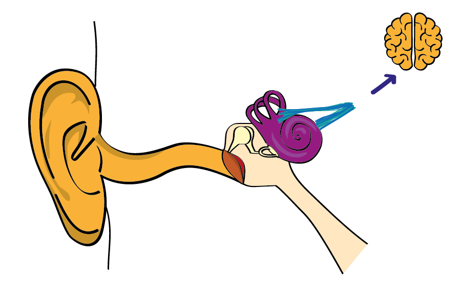
The auditory system, or hearing system, is a complex part of our body that enables us to hear sounds. In
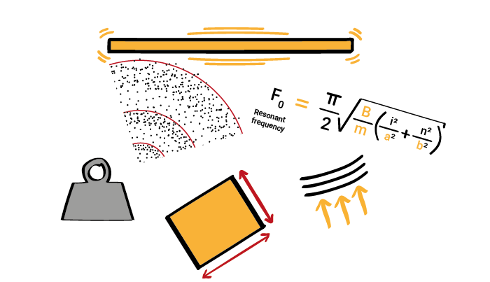
Did you know that panels, made of a solid and non-porous materials, located freely in the air can absorb sound?

Most (99% actually) materials used in construction to absorb sound are porous. And do you know: the 3 differents types
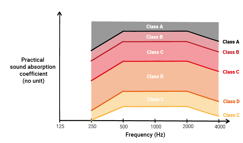
Sound absorption classes are often used to specify sound absorption materials to be installed in buildings. But have you ever
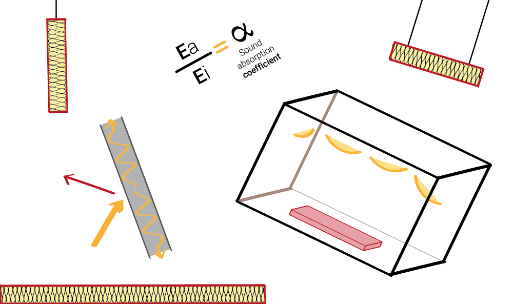
Often, we, acousticians, are asked about the fundamentals of sound absorption. We are also asked to explain sound absorption data
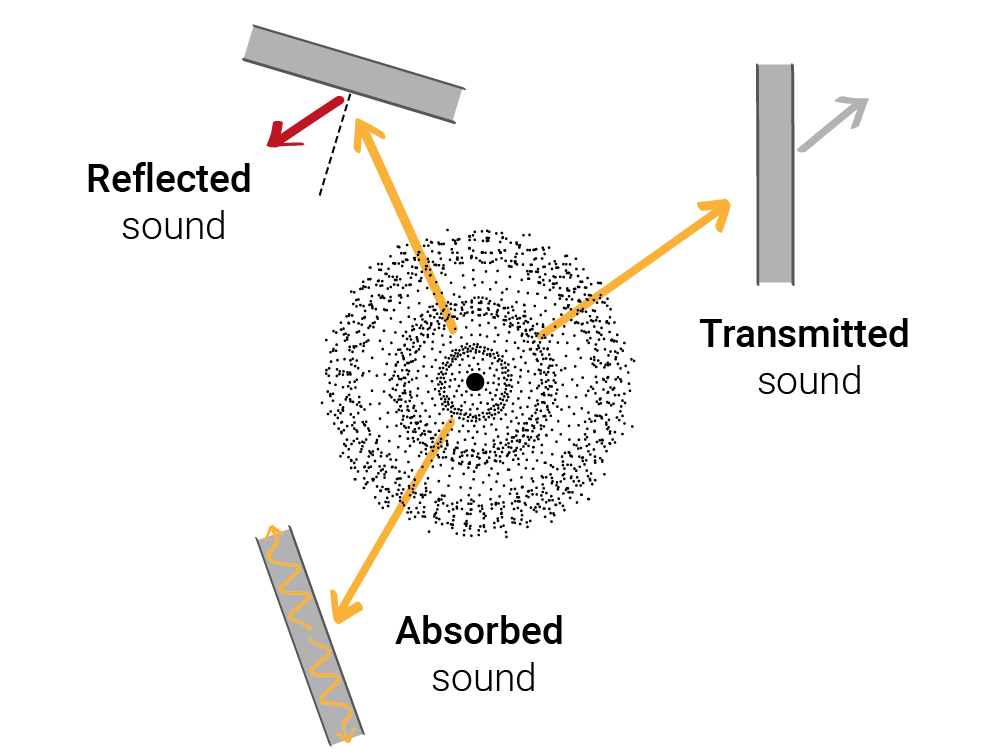
Quite often, we receive questions on how sound propagates, especially through materials. If you need to understand the difference between